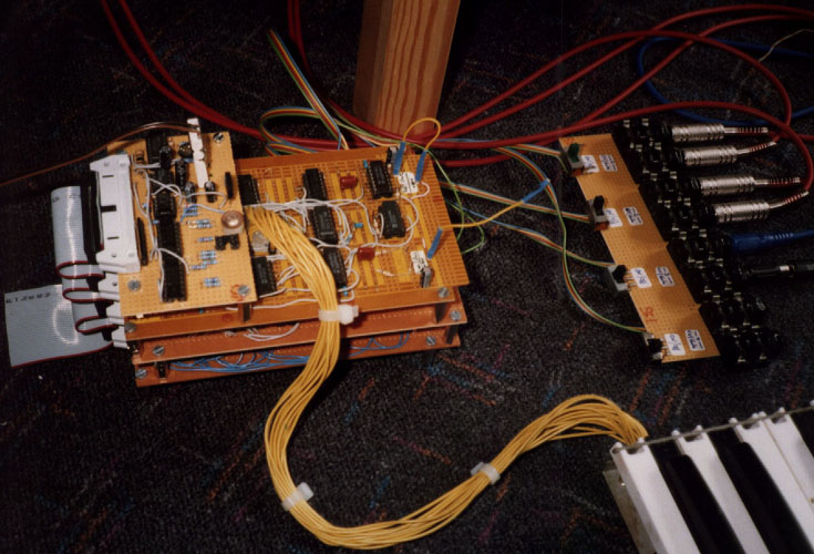
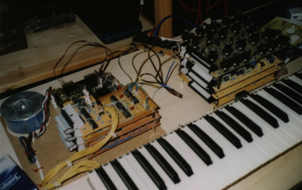
"JH-4" is going to be a DIY polysynth. At the moment, it's a 4-Voice Keyboard Scanner (Photo) and one single Voice Module (Front Panel Layout). But I can already play polyphonic with this one voice, plus my Minimoog Expander, plus two additional voices patched on my JH-3 Modular system.
I was always impressed by the old Oberheim Four Voice,
with its dedicated set of knobs for each voice, and with its unsurpassed
variety of key assign modes. There are some well known shortcomings in
these SEM-based synths, such as only one LFO waveform, only a few parameters
under voltage control, and maybe a few more.
So I decided to build my own version of a SEM module,
plus a clone of the original Oberheim keyboard scanner.
These were my design goals:
* Every parameter must be voltage controlled
* An additional 4-pole filter would be nice
* Generally, a few additional parameters should be added
(see below)
* The whole thing should not have too many knobs (remember
there's a set of knobs for each voice!)
* Build the whole thing as "discrete" as possible. No
integrated circuits in the signal path.
One working Prototype of the JH-4 Voice Module exists,
with 4 pcb boards (200cm x 150cm each) sandwiched together. Some of its
features:
* VCO circuits are very similar to SEM / OB-X
* VCF is a SEM filter clone and a clone of the SSM2040
in parallel. Crossfading from 2-pole LP to Notch to HP to BP to 4-pole
LP is possible. (Manually or with envelope)
* VCA is similar to the Minimoog's, only that it is stereo
with voltage controlled panning function.
* LFO waveform can be crossfaded from Sine to Rectangle
to Sample&Hold to VCO2-SAW. The Sine Wave can be frequency modulated
by an envelope.
There will be a redesign of the VCO board to include the Linear Detuning feature. (Link to Roy Tate's site)
 The
Keyboard Scanner of JH-4 is very
much a clone of the Oberheim 4-voice, without the split mode, but with
all this great variety of assignment modes continuous/reset, reassign,
etc.
The
Keyboard Scanner of JH-4 is very
much a clone of the Oberheim 4-voice, without the split mode, but with
all this great variety of assignment modes continuous/reset, reassign,
etc.
It is build on veroboard, and was tested with the first
JH-4 Voice Module and seveal voices from JH-3 Modular.
On the picture
you see it connected to the keyboard of a dead Polysix.
The Multimode Filter
of JH-4 is a little more advanced than the SEM multimode Filter. There
is an additional
4-pole Low Pass Filter, and the filter mode is completely under voltage
control. No more extra click-stop BP position, either. With a turn of one
knob you have acess to the following modes:
2-pole LP (8 o'clock position),
2-pole Notch (10 o'clock position),
2-pole HP (12 o'clock position)
2-pole BP (2 o'clock position)
4-pole LP (4 o'clock position)
These are the "pure" modes. The transition between 2p-LP
and 2p-HP is exactly like the SEM, with the Notch in between being a mixture
of both (and not really a separate output). There are similar transitions
between the other modes. Especially the mixture between 2p-BP and 4p-LP
can be very pleasant: A fat "Kobol" filter with a bright resonsnce added.
You sweep the filter modes manually, but you can also
use Envelope 1 for that. (Envelope 2 is always routed to the VCF cutoff
control, so you have all degrees of freedom to control Cutoff and Mode
independently. You can also choose which Envelope controls the VCA.) There
are two ways to do the ENV 1 controlled filter sweep. "Positive" will always
start at 2p-LP, and the depth is set with the same knob that you use in
Manual mode. Set it to the cw end position, and the envelope will sweep
thru all modes and back, and will rest at a level set by the Sustain parameter
of the envelope. If you set the knob to some other position, the sweep
range will be reduced. "Negative" will do just the opposite: Start at 4p-LP
and sweep ccw as far as you select the modulation depth.
How does it work ? It is (of course) another application
of my Interpolating Scanner. I don't use the general
version that you will find elsewhere on these pages, but a dedicated
version that is smaller, less precise, only using discrete transistors,
and is a little more difficult to calculate. (Don't be frightened by the
discrete control network - and don't change any resistor value, either
! )
A Block
Diagram will hopefully make clear what's going on in the VCF and VCA
section.
You can see the Prototype (Key assign logic, one voice module, keyboard
from a dead Polysix) here.