
JH. Fixed Filter Bank
The old Moog® Modular System had an option of
two different
Fixed Filter Bank modules, one with 10 bands, and another one with 14
bands.
("Moog" is a
registered Trademark of
Moog Mucic (http://www.moogmusic.com).
Both are very unique-sounding, mostly because of the deep notches
they produce between adjacent filter bands. Some people also claim it's
becuase they used real inductors - wire-wound components that get
nonlinear at higher signal levels. I'm not sure if the latter really is
such an important factor, because thes efilter banks were designed in a
way that in each filter band the signal first passes thru a resonant
LC-filter at a certain level, and then
passes a second LC-filter at a lower
level. So my conclusion would be that the second LC-stage filters out
whatever distortion products may or may not be created in the first
stage. But then again, a tiny amount of harmonocs may survive, and
others may have better ears than I and might hear a difference.
Anyway: I decided to make a PCB that allows both options: real
inductors, or electronic inductors, so you can choose for yourself.
This is possible because I closely stick to the circuit topology of the
original: There are no sallen-and-key or multi-feedback filters inside
(with one exception). It's all passive RLC-Filter design with a an
active driver stage and active summing amp. But you can either choose
to wind your own inductors for the "L" part, or use an active GIC
circuit.
The GIC (General Impedance Converter) circuit is very different from
the one-opamp gyrator circuits that are sometimes used for emulating
Inductors. The GIC has less parasitcs, and most important: it's less
noisy. And in addition to using the GIC technology, which is an
advantage all by itself, I'm also making the circuit as low-Z as
possible: Using 2.2kOhm resistor arrays and opamps that can drive
them without much distortion.
There will be some noise -
just like the original hat some noise, even with all channel
potentiometers set to zero. This is because the channel attenuators
come before the filters. I have kept this topology, too. It has a
certain charm, and it allows the control of each channels level and
overdrive individually. But if you prefer it the other way, you can
also connect the potentiometers after the filters. There are breakout
points of the PCB for this.
You can use 2 PCBs to build a 10-Channel Filter Bank, or 3 PCBs to
build a 14-Channel Filter Bank.
You can choose between a discrete driver amplifier and summing
amplifier, or opamp based amplifiers. With the latter, you can adapt
the filter bank to "modern" 5V synthesizer signals. With the former,
you can be as close to the original as you want.
There is an on-board power supply that only needs a power
transformer and fuses connected, or a wallwart with AC output.
Alternatively, you can use a +/-15V or +/-12V supply voltage as found
in many modular systems.
Pictures of my new (year 2010)
prototype, 907 configuration:
 |
 |
 |
 |
And here's a picture from testing
the 914-style Prototype (3 PCBs, 14 channels)

And a youtube-video (actually, my first youtube video!)
PCB Preview:

And here's what a 1U 19" frontpanel for a standalone 10-Band version
could look like:

Schaeffer AG Frontplattendesigner file
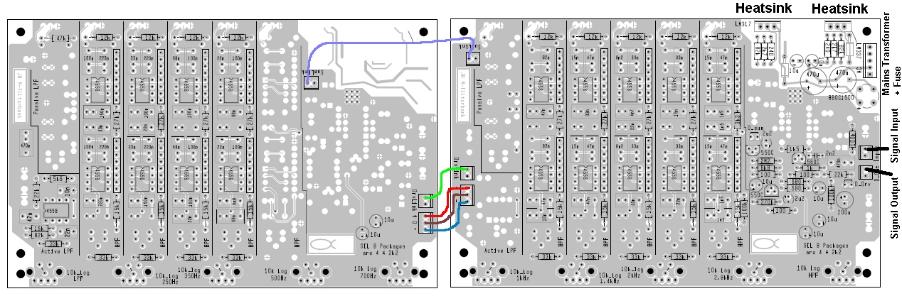
How to connect the boards.
Example: 907-style 10-Band Filterbank with discrete driver and summing
amp and on-board power supply.
"Low" board (with LPF and lower BPFs) on the left, and "High" board
(with higher BPFs, HPF, Amplifiers and PSU) on the right:
You can either solder Alps RK11 potentiometers directly into the
PCBs, or connect whatever brand of potentiometers you like, with wires.
IMPORTANT
construction note
As these PCBs can be used for different versions of a filterbank, the
component values printed on the PCB may not be the same as you have to
solder into your version of the filterbank! The whole project was first
intended for a 907-style 10-band filterbank. Then I noticed the same
boards can also be used for a 914-style 14-band filterbank, with only a
few additions, and 3 boards instead of two.
Some components are simply not used in some versions: No trimpots for
the 10-band filterbank, for instance. The 14-band filterbank has a
trimpot and a fixed resistor in series connection for each band. The
10-band filterbank only has the resistor. That resistor goes to a
different hole in the 10-band version on one side (to bridge the
trimpot that is only used in the 14-band version). If you carefully
check the component overlays on this web side (see below), everything
schould be clear. Just don't stuff the PCBs blindly with everything
that's printed onto it, or you'll have to desolder a lot of components.
:)
Comment about 14-Band ("914")
version
At first, this was clearly intended as a 10-Band filterbank project, to
emulate the famour 907 fixed filter bank. But due to public demand I
adapted the boards to be used for a 14-band version ("914") also: Use 3
PCBs instead of 2, and put in different components in the filter
channels. Only when the board design was finished, I became aware that
the original 914 has a different summing amplifier topology, too: Where
the 907 uses an approximated virtual GND / inverting amplifier summing,
the 914 uses passive summing with a noninverting high-gain amplifier to
restore the level. This includes an extra quirk: a high pass filter
between the passive summing node and the output amp. I decided to
emulate this as closely as possible, and I think I succeeded. This,
however, involves soldering components diagonally across the PCB, and
adding some extra wires - my apologies for this! But I think it
reproduces the behaviour of the original quite faithfully.
Component overlay for various
options:
907-Style "Low" board with active filters
(GIC inductance simulation)
907-Style "High" board with
active filters (GIC inductance simulation), discrete driver and summing
amplifier, and on-board power supply
907-Style "High" board with
active filters (GIC inductance simulation), OpAmp driver and summing
amplifier, and MOTM connector for +/-15V DC (also works with +/-12V)
907-Style "Low" board with
wirewound inductors
907-Style "High"
board with wirewound inductors,
discrete driver and summing amplifier, and on-board power supply
914-Style "Low" board with active
filters (GIC inductance simulation)
914-Style "Mid" board with active
filters (GIC inductance simulation)
updated: 914-Style "High" board with active
filters (GIC inductance simulation),
on-board power supply
updated: 914-Style "High" board with active
filters (GIC inductance simulation), MOTM connector for +/-15V DC (also
works with +/-12V)
(use NE5532 instead of OPA2134)
Schematics for various options:
907-Style with active filters (GIC
inductance simulation), discrete driver and summing amplifier, and
on-board power supply
907-Style with active filters (GIC inductance
simulation), +/-15V or +/-12V power supply (for MOTM or other modular
systems)
new: 914-Style input- and output-amps (passive
summing and noninverting amplifier - different from 907 version!)
Will be continued ....